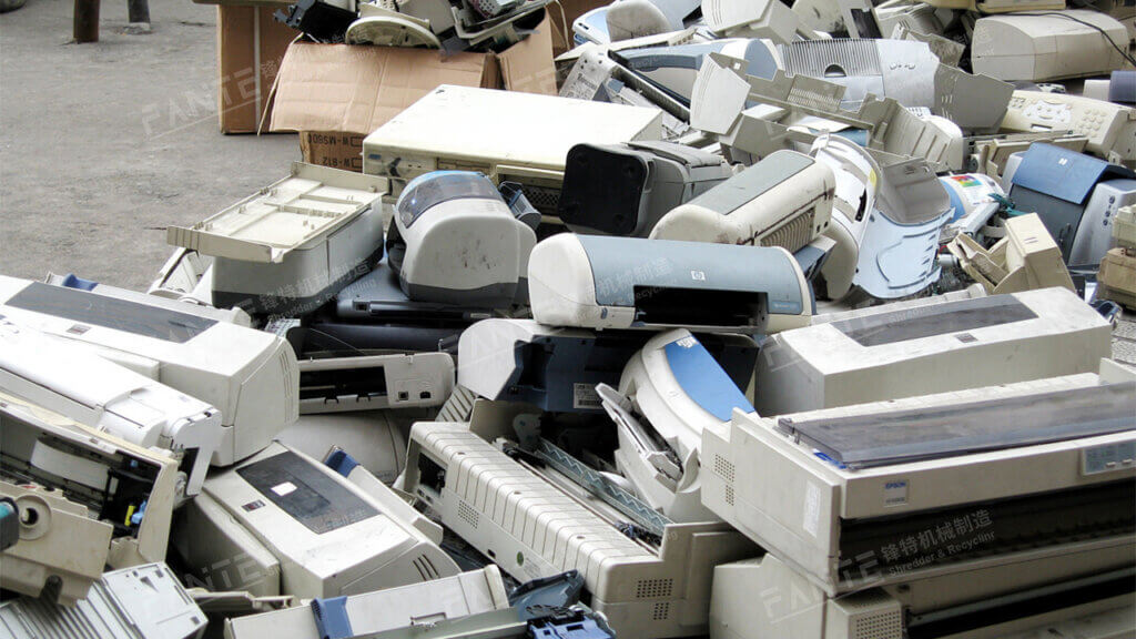
There are many types of printers, and the disassembly methods are also different. Here, we take a dot matrix printer as an example to introduce its disassembly process
(1) Disassembly of the printer paper feed device
- ① Turn the printer power switch to the OFF position and disconnect all data cables and power cables connected to the printer
- ② Remove the printing paper. When removing the paper, be sure to lift the paper wrench vertically to remove the printing paper.
- ③ Disassemble the printing paper bracket. The bracket is inserted into the chassis with slots on both sides. When disassembling, just lift the bracket and pull it up with force.
- ④ Disassemble the observation cover. The observation cover is also stuck on both sides of the chassis. When disassembling, just lift it and pull it up. Note that the observation cover is connected to a cover on the base. Remove it together when disassembling.
- ⑤ Disassemble the top cover. Use a screwdriver to unscrew the fixing screws of the top cover. Press the top cover tab toward the front panel from the front panel. Use your other hand to grab the top cover and pull it up, then pull it forward and upward. Then pull out the wire plug of the control key on the top cover, lift the left side, and then slide the top cover to the right to make it away from the paper feed shaft. The top cover can be removed. There are two tabs on the top cover.
- ⑥ Turn the bolt handle forward to the release position.
- ⑦ Loosen the nuts at both ends of the support shaft of the paper feed device.
- ⑧ Remove the left fixing clip of the guide shaft and slide the bushing out of the frame from the shaft.
- ⑨ Lift the guide shaft, support shaft and printing paper traction device from the machine.
- ⑩ Slide the printing paper traction device off the shaft.
(2) Disassembly of the fuse-filter circuit board/AC socket
- ① Disassemble the safety cover of the fuse-filter circuit board assembly.
- ② Remove the primary connector of the power transformer from the fuse-filter circuit board. ③ Remove the screw in the middle of the fuse-filter circuit board.
- ④ Remove the screw on the ground wire of the AC socket.
- ⑤ Remove the AC socket from the base slot.
- ⑥ Remove the fuse-filter circuit board from the base slot.
- ⑦ Unplug the sockets connected to the switch, power socket, and circuit board power lead from the circuit board. If they are directly soldered, use a soldering iron to solder them off or cut them off with pliers.
- ⑧ Remove the power switch from the side cover of the chassis. When disassembling, hold the switch body with your hands or needle-nose pliers and pull it up.
- ⑨ Use the same method to remove the three-pin power socket from the rear cover.
(3) Disassembly of the intermediate gear
- ① Remove the two screws on the paper feed motor bracket.
- ② Remove the fixing clip of the intermediate gear.
- ③ Remove the sliding traction shaft of the intermediate gear
(4) Disassembly of the left end positioning sensor
- ① Move the carriage to the right shelf.
- ② Remove the fixing screws and clips that secure the sensor.
- ③ Solder the three wires on the left end of the positioning sensor.
- ④ Pick up the left end positioning sensor from the printer.
(5) Disassembly of the power transformer
- ① The power transformer is installed on the power circuit board. When disassembling, you must first remove the power circuit board. First, use a soldering iron to solder the transformer pins from the circuit board.
- ② Generally, because the transformer is heavy, it is fixed with screws in addition to soldering. Use a screwdriver to unscrew the fixing screws, firmly grasp the transformer and pull it upwards, and then you can remove the transformer from the power board.
(6) Disassembly of the print head
- ① Use the above method to disassemble the paper holder, observation cover, and top cover.
- ② Pull the print head cable from the connector. Apply even force when pulling, and pull from the back of the print head.
- ③ Pull the two latches on the print head to the sides, grasp the heat sink of the print head and pull it upwards, and then you can remove the print head from the carriage.
(7) Disassembly of the printer mechanical assembly
- ① Use the above method to disassemble the paper tray, observation cover, and top cover.
- ② Remove the fixing screws at the bottom of the printer’s mechanical assembly. Be sure to remove all screws.
- ③ Unplug all wires connected to the circuit board, power board, and control board.
- ④ Lift the printer’s mechanical assembly from the base.
(8) Disassembly of the ribbon cassette
- ① Use the above method to disassemble the paper tray, observation cover, top cover, and print head.
- ② Remove the ribbon cassette. The ribbon cassette is directly installed on the printer mechanical assembly. Just gently lift the ribbon cassette from the right side.
- ③ Disassemble the ribbon in the ribbon cassette. Pry open the ribbon cassette’s tab with your hands or needle-nosed pliers.
- ④ Remove the ribbon from the ribbon cassette and remove the screw adjuster assembly used to adjust the ribbon tension.
(9) Disassembly of the control circuit board
- ① First, disassemble the paper tray, top cover, and mechanical device using the above method.
- ② Remove the connecting wires to all control mechanisms and other circuit boards.
- ③ Find the fixing screws that fix the control circuit board and unscrew them with a screwdriver.
- ④ Remove the circuit board from the chassis.
(10) Disassembly of the power transistor and heat sink
- ① Use a screwdriver to remove the screws that fix the heat sink. If some heat sinks are still soldered to the circuit board, use a soldering iron to solder them off.
- ② Use a soldering iron to remove the power transistor from the circuit board.
(11) Disassembly of the carriage belt
- ① Remove the screws on the left front and right sides of the carriage motor bracket.
- ② Lift the motor off the bracket to expose the belt pulley.
- ③ Pull the belt off the clip under the print head carriage.
- ④ Loosen the screws in the slot on the carriage drive assembly.
- ⑤ Move the carriage drive assembly to the right. ⑥ Disconnect the belt from the pulleys at each end.
- ⑦ Pull out the belt from the opening on the right side of the printer mechanism assembly.
(12) Disassembly of the carriage drive assembly
- ① Move the carriage to the right side of the frame.
- ② Loosen the carriage slide shaft and unscrew the left end of the shaft forward.
- ③ Remove the screws and clips on the left end positioning sensor.
- ④ Remove the fixing screws of the carriage drive assembly.
- ⑤ Turn the carriage drive assembly clockwise to disengage the belt from the drive pulley, lift the left end positioning sensor off the positioning bolt, and then lift the carriage drive assembly from the machine.
(13) Disassembly of the printer control panel
- ① Disassemble the top cover.
- ② Invert the top cover.
- ③ Remove the two screws from the inside of the top cover.
- ④ Lift the control panel from the top cover.